Understanding the Basics of Automotive Circuit Diagrams
Ever looked at an automotive circuit diagram and felt like you were staring at an alien language? Don’t worry—you’re not alone. These diagrams may seem intimidating at first, but they’re essentially the blueprint of your car’s electrical system. By understanding the basics, you’ll unlock the mystery behind how your vehicle’s electrical components connect and function together.
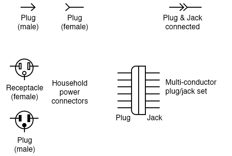
Automotive circuit diagrams use standardized connector symbol to represent components like batteries, switches, fuses, and wires. These symbols help technicians identify parts and their connections quickly. For instance, a simple line represents a wire, while a zigzag line might indicate a resistor. Once you grasp these fundamentals, you’ll see how each part plays a role in powering everything from your headlights to your infotainment system.
Decoding Automotive Connector Symbol
Connectors are the unsung heroes of your car’s electrical system—they link various components to ensure everything works seamlessly. But what do those cryptic symbols on a circuit diagram mean? Let’s break it down.
Connector symbols often include shapes like rectangles or circles with letters and numbers inside them. These identifiers specify the type of connector and its pin configuration. For example:
Rectangular connectors are commonly used for multi-pin connections, such as those linking your car’s ECU (Engine Control Unit) to sensors.
Circular connectors might be found in areas requiring robust sealing, like under the hood.

To make this easier to visualize, imagine a rectangle labeled “C101.” This symbol might represent a 10-pin connector located near the engine bay. Each pin would have its own unique number for identification, helping technicians trace wires accurately during repairs.
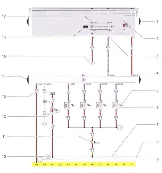
Connector symbol Circuit schematic illustration
1-Triangular arrow, indicates the wiring diagram on the next page.
2-Fuse designation, S5 in the diagram indicates that the fuse is located in position 5 of the fuse block, 10 amps.
3-Plug connection designation on the relay board, indicates multi-pin or single pin plug connection and wire location, e.g., D13 indicates multi-pin plug connection, D position contact 13.
4-Terminal designation, indicating the number of terminals on the electrical component/multi-pin plug connection contact number.
5-Component designation, the name of the component can be found at the bottom of the circuit diagram.
6 – Symbol of the component, can be found in the circuit diagram symbol description.
7-Internal wiring (thin solid line), which is not set up as a wire, but indicates the circuit inside the component or wire bundle.
8-Indicates where the internal wiring goes, the letter indicates that the internal wiring is connected to the internal wiring labelled with the same letter on the next page of the wiring diagram.
9 – The designation of the grounding point, which can be found under the wiring diagram to find the location of the designation of the grounding point on the vehicle.
10 – Designation of the connection in the wiring harness, under the wiring diagram you can find out where the non-removable connection is located in the wiring harness.
11 – Plug connection, e.g. T8a/6 means 8-pin a plug contact 6.
12 – Additional fuse symbols, e.g. S123 indicates fuse position 23, 10 amperes, on the central electrical additional relay board.
13-Colour and cross-sectional area of the wires (in square millimetres).
14-Triangular arrow indicating the component connected to the previous page of the wiring diagram.
15-Indicates where the wire goes, the number in the box indicates to which contact number the wire is connected.
16-Relay position number, indicates the relay position number on the relay board.
17-Relay or controller wiring designator on the relay board, which indicates the individual contacts of the relay multi-pin plug. For example, 2/30 indicates: 2=contact 2 for position 2 socket on the relay board, 30=contact 30 on the relay/controller.
Real-World Application of Connector Symbols in Automotive Circuit Diagrams
Theory is great, but how do these symbols come into play in real-life scenarios? Picture this: Your car’s air conditioning suddenly stops working. A technician pulls up the circuit diagram and identifies a connector symbol linked to the AC control module. By tracing this symbol to its physical counterpart in your car, they discover a loose connection causing the issue.
In modern cars, these symbols are also used in conjunction with digitisation tools. For example, some advanced diagnostic instruments can read the wiring diagram directly and mark the connector location corresponding to the point of failure via the device display. This technology further enhances the efficiency of repairs while reducing the reliance on the technician’s level of experience.
In summary, whether it is a simple fault or a complex problem, automotive connector symbols are like road signs on a map, providing clear guidance for repairers. Mastering these symbols not only improves repair efficiency, but also reduces misjudgements and unnecessary repair costs, thus bringing a better service experience to vehicle owners.

Understanding automotive connector symbol isn’t just about fixing cars—it’s about empowering yourself with knowledge that saves time, money, and frustration. Whether you’re troubleshooting an electrical issue or customizing your ride, knowing how to read these symbols gives you a significant edge.