
Connector symbols are the unsung heroes of electronics and programming. They provide a universal language for representing relationships between components or modules, making complex systems comprehensible. In electronics, these symbols simplify circuit design and troubleshooting by graphically representing components and their connections. Meanwhile, in programming, connector symbols facilitate seamless interaction between variables, functions, and memory addresses. This article takes you on a journey from foundational concepts to advanced applications of connector symbols, equipping you with the knowledge to use them effectively in your projects.
Basic Concepts of Connector Symbols
Connector Symbols in Electronics
Connector symbols in electronics are standardized graphical representations used in schematic diagrams to denote components like resistors, capacitors, diodes, and more. They serve as the blueprint for understanding how electrical systems function.
- Purpose: These symbols ensure clarity and consistency in circuit design, enabling engineers worldwide to communicate effectively.
- Examples:
- A resistor is represented by a zigzag line or a rectangle and limits current flow.
- A capacitor uses two parallel lines (one curved for polarized types) and stores electrical energy.
- A diode is depicted with an arrow pointing to a line, illustrating current flow direction.

Connector Symbols in Programming
In programming, connector symbol represent identifiers like function names or variable names that link different parts of a program. These symbols play a pivotal role in modular programming by managing dependencies between code modules.
- Purpose: They ensure smooth communication between program components, much like connectors in electronics enable the flow of current between devices.
- Categories:
- Global Symbols: Accessible across multiple modules (e.g., public variables).
- Local Symbols: Restricted to specific modules (e.g., static variables).
Detailed Analysis of Electronics Connector Symbols
Common Electronic Components and Their Symbols
Understanding the symbols for common electronic components is crucial for reading and designing schematics:
Resistors: Represent resistance to current flow; essential for controlling voltage and current in circuits.

Capacitors: Store electrical energy temporarily; vital for filtering noise or stabilizing power supply outputs.

Inductors: Represent coiled wires that store energy magnetically; used in oscillators or filters.

Diodes: Allow current to flow in one direction; include LEDs (light-emitting diodes) and Zener diodes for voltage regulation.

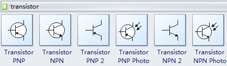
Transistors: Amplify signals or act as switches; include NPN and PNP types.
Standards for Electronic Symbols
To avoid confusion, electronic symbols adhere to international standards:
- IEC 60617: Widely used globally for graphical symbols.
- ANSI Y32.2/IEEE Std 315: Commonly adopted in North America.
- JIC Standards: Used in industrial applications.
Practical Example
Consider a DC power supply circuit:
- Diodes form a bridge rectifier to convert AC to DC.
- Capacitors filter out ripples for a steady output.
- Resistors limit current to protect sensitive components.
Detailed Analysis of Programming Connector Symbols
Symbol Tables and Linking Process
In programming, connector symbols are managed during the linking process:
- A symbol table stores information about identifiers like variable names and memory locations.
- The linker resolves dependencies between modules by combining multiple object files into an executable program.
Strong vs Weak Symbols
Connector symbols can be classified as strong or weak based on their behavior during linking:
- Strong Symbols:
- Must be unique within the program.
- Example: Defined global variables or functions.
- Weak Symbols:
- Can be overridden by strong symbols.
- Example: Default implementations of library functions.
Static vs Dynamic Linking
Linking can occur at different stages of program execution:
- Static Linking:
- Combines all dependencies during compilation.
- Results in larger executables but faster runtime performance.
- Example: Embedded systems often use static linking for reliability.
- Dynamic Linking:
- Loads dependencies at runtime, reducing file size but increasing load time.
- Example: Shared libraries (.dll files) used in modern operating systems.

Advanced Applications of Connector Symbols
Advanced Applications in Electronics
Electronics design often involves complex systems where efficient management of connector symbols is critical:
- Multi-layer PCB Design:
- Connector symbols help manage interconnections across layers using through-hole vias or surface-mount pads.
- Example: EDA tools like Altium Designer automate symbol placement for multi-layer designs.
- Modular Circuit Design:
- Breaking down circuits into reusable modules simplifies troubleshooting and upgrades.
- Example: Audio amplifiers often separate preamp, power amp, and tone control stages.
Advanced Applications in Programming
Programming benefits from optimized use of connector symbols:
- Custom Linker Scripts:
- Control memory layout by placing critical code sections into high-speed memory regions.
- Example: Real-time operating systems (RTOS) use linker scripts to prioritize interrupt handlers.
- Symbol Versioning:
- Ensures backward compatibility by exporting specific versions of dynamic library interfaces.
- Example: Linux’s glibc uses symbol versioning to maintain compatibility across updates.
—
This article has explored the significance of connector symbols across electronics and programming domains, highlighting their role as essential tools for design and communication. By mastering these concepts—from basic resistor diagrams to advanced linker scripts—you can enhance your efficiency and precision when working on complex projects. Whether you’re troubleshooting a circuit or optimizing software performance, understanding connector symbols will empower you to build robust solutions with confidence.